Modular 3D-Printed Wooden 19" Server Frame for Home Labs
A lightweight, customizable rack frame made from 3D-printed connectors and 25 mm wooden rods. The calculator helps determine cut lengths for different rack heights and hardware depths.
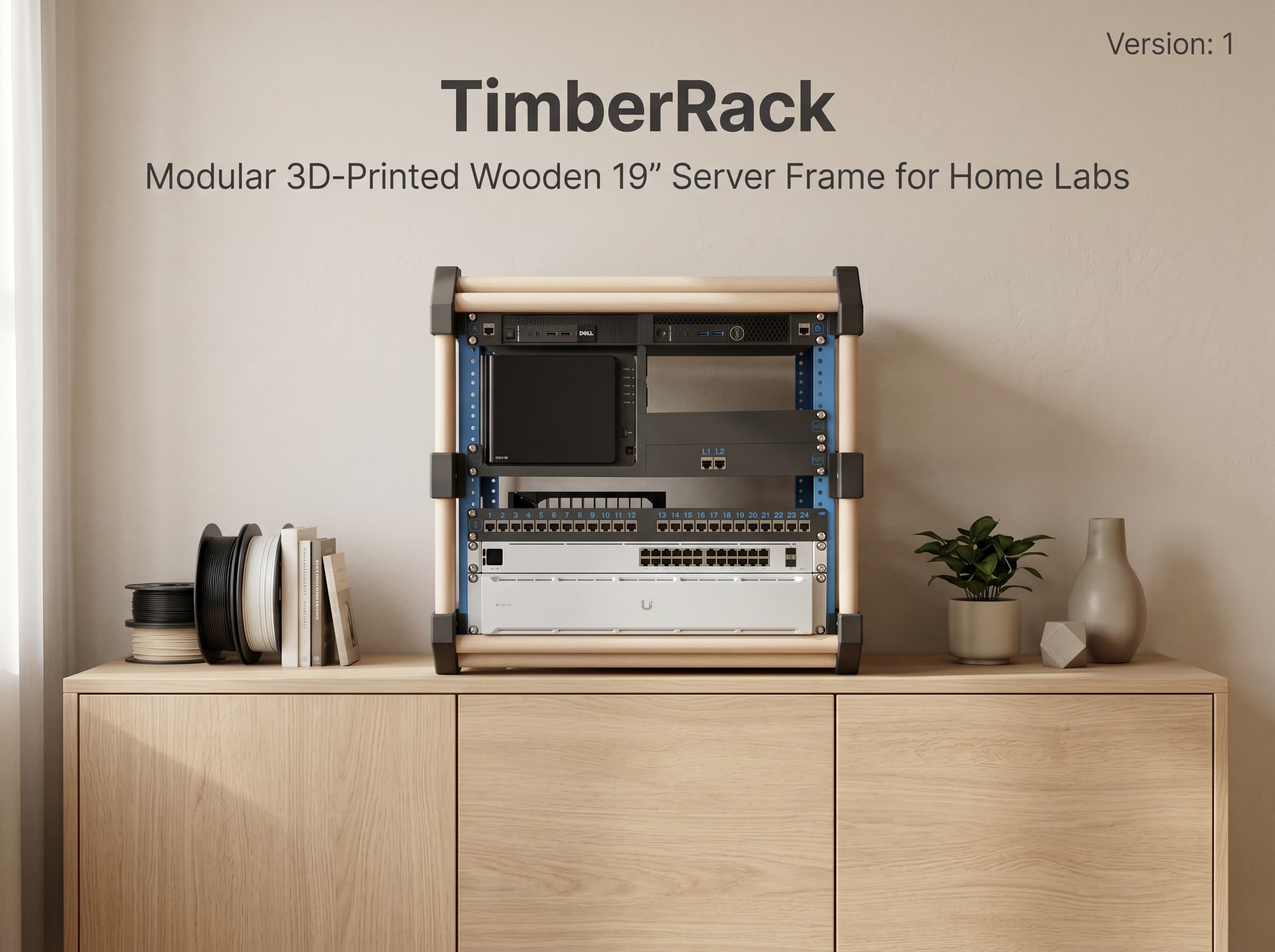
Modular construction
Stackable base design with 3U, 4U, 5U and 6U rail variants.
Simple materials
3D-printed connectors, 25 mm wooden rods and standard screws.
Parts & cut list for your TimberRack
Enter rack height, depth and stock rod length. The calculator turns that into a parts list for wooden rods, 3D printed parts, screws, inserts and the optimized cutting plan.
Measurements
1 rack unit equals 44.45 mm. A total of 18 mm is subtracted for the mounting offset.
Height calculation
(44.45 mm x 10 U) - 18 mm = 426.5 mm
Parts list & material needs
Calculates wooden rods, stock rods, 3D printed parts, screws and inserts from your current inputs.
Recommended rail combination
This split is built per rail column. The parts list below is calculated for front and rear rails on both rack sides.
Total rods
25
Total printed parts
30
Total screws/inserts
94
Wooden rods
3D printed parts
Screws & inserts
Smart cutting plan
The optimizer distributes all required wooden pieces across your stock rod length and accounts for the saw kerf.
Required stock rods
12
Total waste incl. kerf
1,189 mm
Material usage
90.09 %
Stock rod 1
used incl. cuts: 993.5 mm · offcut: 6.5 mm
Stock rod 2
used incl. cuts: 993.5 mm · offcut: 6.5 mm
Stock rod 3
used incl. cuts: 993.5 mm · offcut: 6.5 mm
Stock rod 4
used incl. cuts: 993.5 mm · offcut: 6.5 mm
Stock rod 5
used incl. cuts: 993.5 mm · offcut: 6.5 mm
Stock rod 6
used incl. cuts: 993.5 mm · offcut: 6.5 mm
Stock rod 7
used incl. cuts: 993.5 mm · offcut: 6.5 mm
Stock rod 8
used incl. cuts: 993.5 mm · offcut: 6.5 mm
Stock rod 9
used incl. cuts: 909 mm · offcut: 91 mm
Stock rod 10
used incl. cuts: 909 mm · offcut: 91 mm
Stock rod 11
used incl. cuts: 817 mm · offcut: 183 mm
Stock rod 12
used incl. cuts: 303 mm · offcut: 697 mm
Note: The plan counts one kerf per part. If you can use an end piece without an additional cut, the real offcut will be slightly larger.
Assembly guide
The guide walks through preparing the printed parts, building the two side frames and closing the final frame.
Prepare the corner brackets
First install the threaded inserts in the corner brackets, then screw on the matching rail mounts.
- All 8 corner brackets get 2 M4 inserts each.
- Each Corner Bracket (CB) pairs with one Rail Mount (RM).
- Each Corner Bracket - Mirrored (CB-M) pairs with one Rail Mount - Mirrored (RM-M).
- The codes in parentheses are printed onto the parts with a -0.2 mm offset so you can identify them clearly.
- Each RM/RM-M is attached to the matching corner bracket with 2x M4 x 12 mm screws.
- The rail mounts must sit flush so the blue rack rails are guided straight later.
Preparation steps
Install the inserts first, then screw RM and RM-M onto the matching corner brackets.
Install 2x M4 inserts in each corner bracket
Attach RM and RM-M with 2x M4 x 12 mm screws
Assemble the side frames
Build one side frame completely first, then repeat the process mirrored for the second side.
- The rail mounts (RM/RM-M) must face inward toward the rack rails later.
- Use Bottom Load Support - Mirrored (BLS-M) for the left side and Bottom Load Support (BLS) for the right side.
- Both side frames need the same rail split and the same rack height.
Prepare the upper and lower assemblies
At the top, insert the width wooden rods into one Corner Bracket first and then into one Corner Bracket - Mirrored. At the bottom, slide the matching Bottom Load Support onto the rods first, then add the Corner Bracket - Mirrored and the Corner Bracket.
Prepare the vertical rod pairs
Prepare the two rod pairs for the rack height. If your rail split requires Rail Extension Blocks, slide them onto the wooden rods now and place them roughly at the later rail joints.
Connect multi-piece rails
If a rail column consists of several rail segments, slide the rails onto the Rail Extension Blocks from the outside. At this point they are only connected, not finally aligned.
Insert single-piece rails directly
If only one rail is needed per rail column, skip the Rail Extension Blocks and insert the rail directly into the upper part of the side frame from below.
Finish assembling the side frame
Now push the upper and lower assemblies onto the two vertical rod pairs. Make sure the rails slide cleanly into the rail mounts. For single-rail setups it is easier to slide both vertical rod pairs into the upper assembly first, then insert everything into the lower assembly together.
Finished side frames
This is how the left and right side should look at the end of step 1. Check the rail mounts, rails and Bottom Load Support alignment especially carefully.
Finished left side frame
Finished right side frame
Final assembly
Connect the two finished side frames with the width wooden rods and close the frame into the complete TimberRack.
- Work on a flat surface so the frame does not twist while being assembled.
- Insert the width wooden rods loosely first and tighten the screws only at the end.
- Before tightening, check that all corners are fully seated and the 19-inch rails are parallel.
Connect the lower frame
Stand both finished side frames upright and connect them at the bottom with the width wooden rods. Start at one corner and work around the frame so it can still move slightly during alignment.
Close the upper frame
Insert the upper width wooden rods and slide the second side on evenly. The rails must face inward and all rods must be fully seated in their sockets.
Align the frame
Press all joints together evenly, square up the rack and check that the front and rear rails are parallel.
Check the finished TimberRack
Finally tighten all screws, check that the rack stands evenly and inspect the rail mounts and Rail Extension Blocks. The frame is then ready for hardware.